- Español
- Português
- русский
- Français
- 日本語
- Deutsch
- tiếng Việt
- Italiano
- Nederlands
- ภาษาไทย
- Polski
- 한국어
- Svenska
- magyar
- Malay
- বাংলা ভাষার
- Dansk
- Suomi
- हिन्दी
- Pilipino
- Türkçe
- Gaeilge
- العربية
- Indonesia
- Norsk
- تمل
- český
- ελληνικά
- український
- Javanese
- فارسی
- தமிழ்
- తెలుగు
- नेपाली
- Burmese
- български
- ລາວ
- Latine
- Қазақша
- Euskal
- Azərbaycan
- Slovenský jazyk
- Македонски
- Lietuvos
- Eesti Keel
- Română
- Slovenski
- मराठी
- Srpski језик


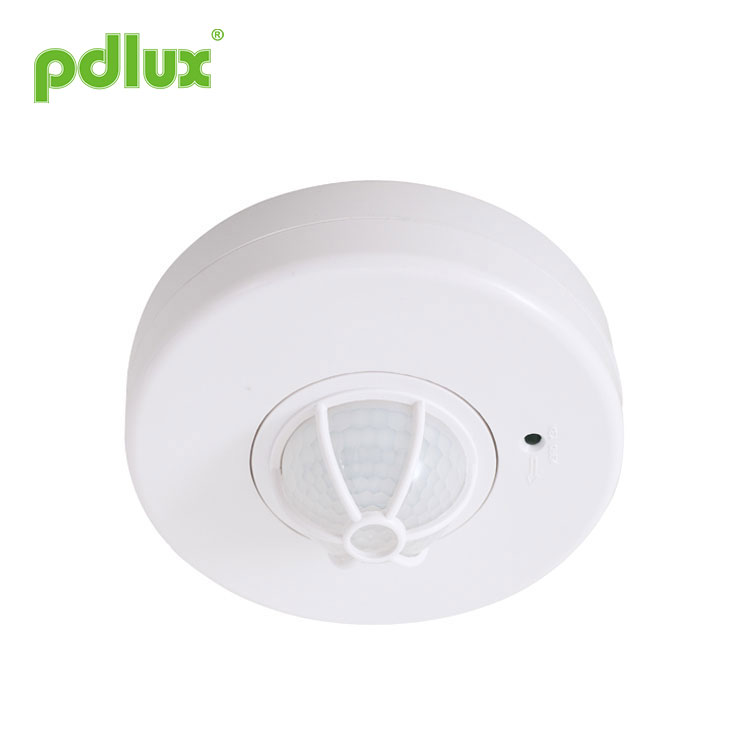
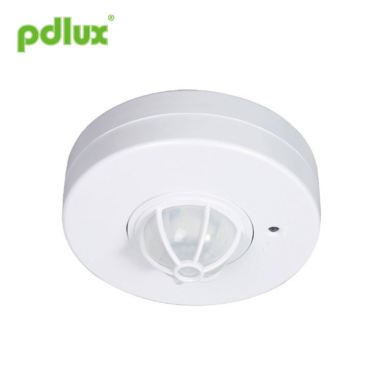
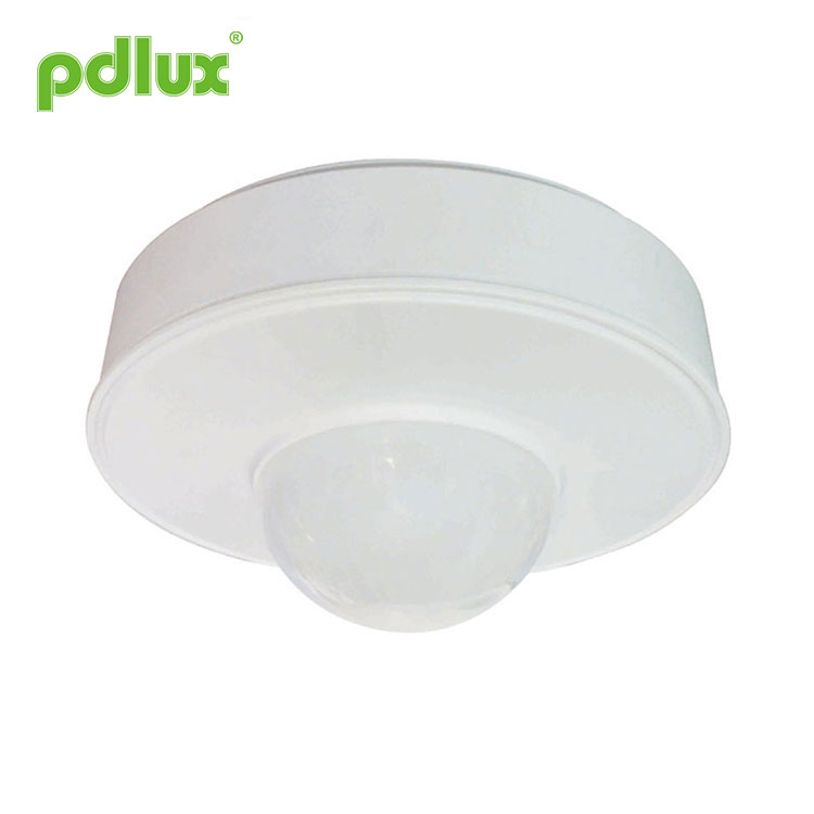
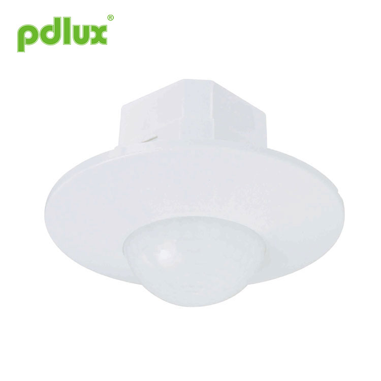
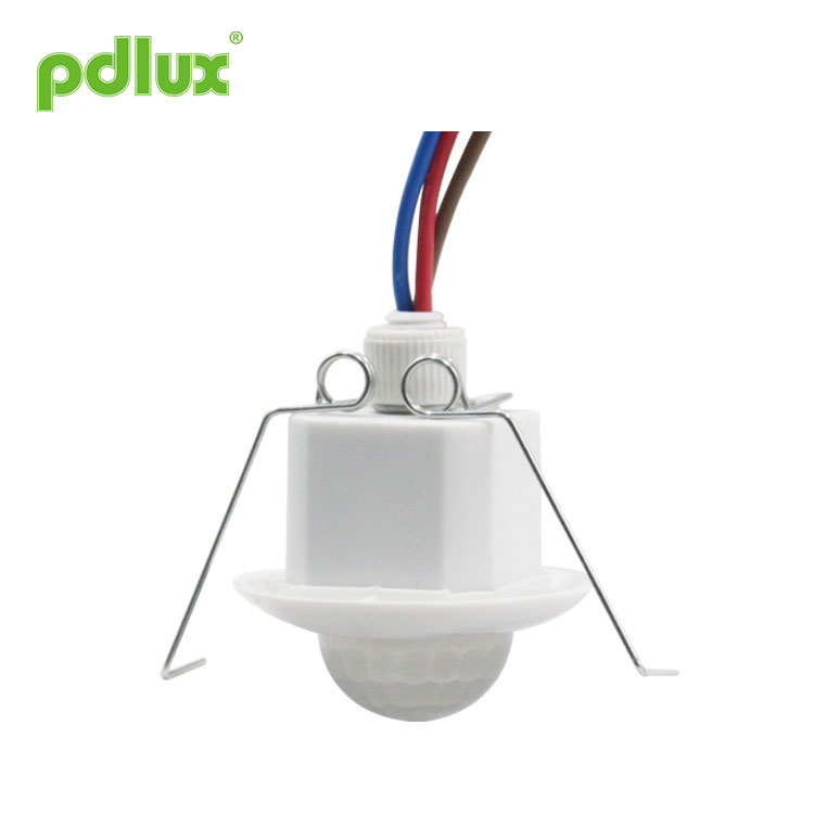
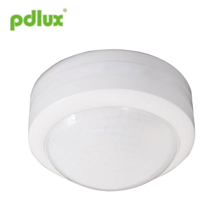
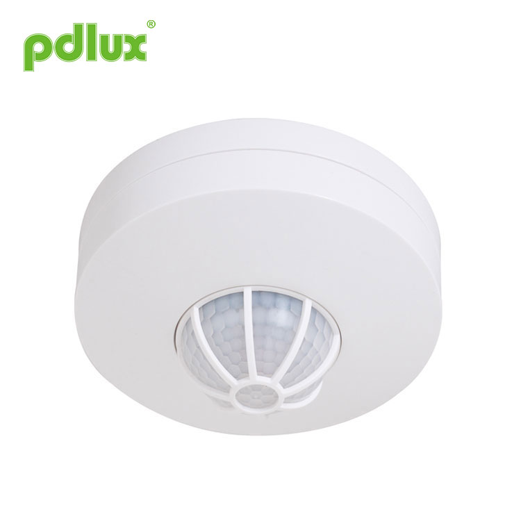
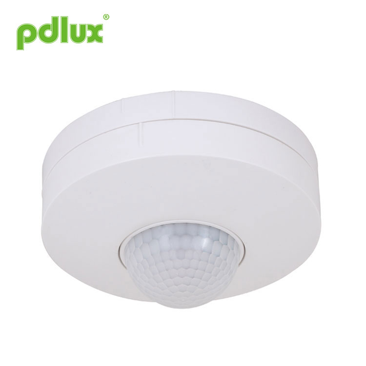
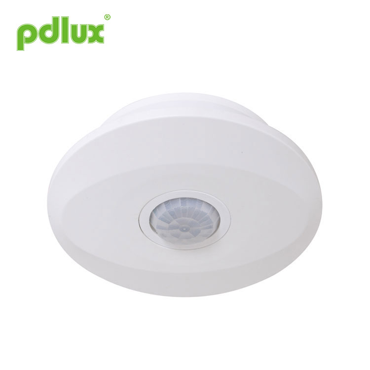
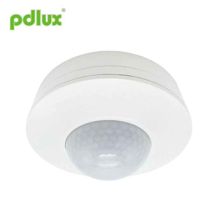
360° Detection Infrared Sensor
PDLUX PD-30N2
360° Detection Infrared Sensor uses a digital information processing system. The easiest way to consider the 30N2 at the start of the design is to remove the front frame of the sensor and select the appropriate location for each function to be replaced.
Send Inquiry
Product Description
Infrared Sensor 30N2
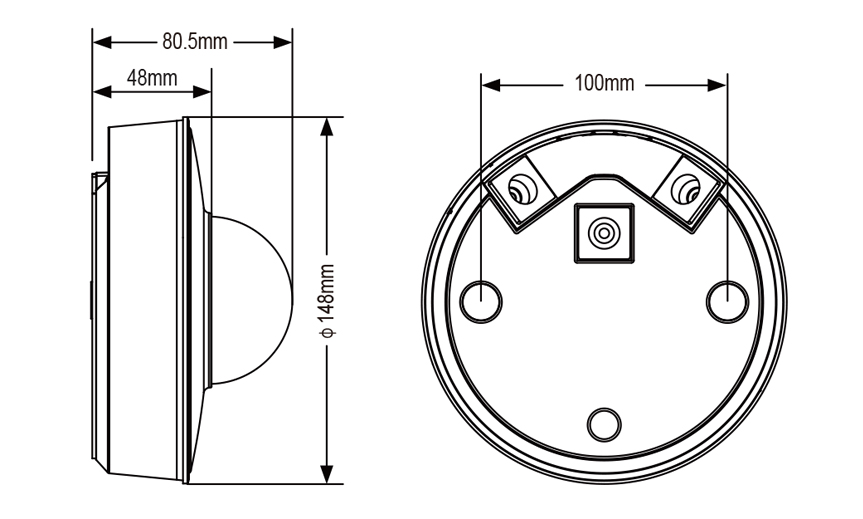
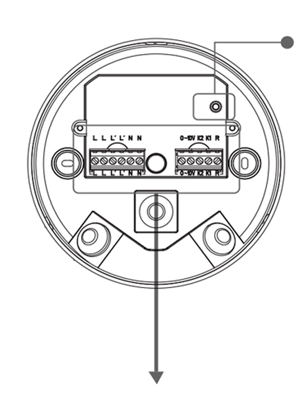
Product size
Summary
360° Detection Infrared Sensor is a completely new concept design with its output control section completely separated from the sensor section. The bottom of the box can be wired. It completely overcomes the problem of traditional wiring connections. The sensor components and control components use wireless connectivity technology. The sensor section is completely separate from the output control section and is extremely easy to operate and easy to install. Fixed product only needs two the screws make the installation of the sensor simple. 360° Detection Infrared Sensor is a completely revolutionary design. This is our patented product.
360° Detection Infrared Sensor uses a digital information processing system. The easiest way to consider the 30N2 at the start of the design is to remove the front frame of the sensor and select the appropriate location for each function to be replaced.
360° Detection Infrared Sensor can withstand a wide voltage of 100V-277V and can be used in any country in the world. Standby power consumption <0.5W, powerful, with dual control outputs, high power output can control any load of 2300W, and the second output can control any load of 1000W. There is also a 0-10V brightness control port for controlling the brightness of the dimming light. You can set the percentage of standby brightness. 30N2 Considering the needs of different users, we have reserved space for further expansion. Users are welcome to ask about your needs. We are always ready to add the features you need.
Please read the following sections of this manual carefully for installation and operation.
Specifications of 360° Detection Infrared Sensor
Power supply Voltage: 100-277V,50/60Hz
Main control:
Power: 2300W/230V Max 3000W/230V
Auxiliary control:
Power: 1000W/230V Max 1200W/230V
Dimming control: 0-10V 50mA
Delay: 10 sec-20 minutes (adjustable)
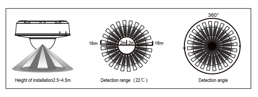
Detection Distance: 2-16m (radii.)/22°C.(adjustable)
Standby time: off / 10min/ 20min/ constant light
Standby brightness: 5%, 10%, 20%, 30%
Optical control Illumination: <10LUX~2000LUX (adjustable)
Detection angle: 360°
Mounting Height: 2.5m-4.5m
Operating Temperature: -10 - +40°C
Probe movement speed: 0.6-1.5m/s
relative Humidity: <93%RH
Static power consumption:<0.5W
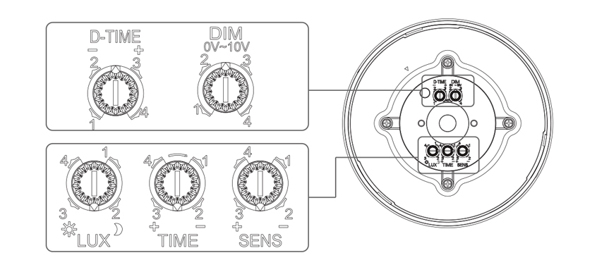
Feature Settings description
1. Sensitivity adjustment knob:
Sensitivity adjustment knob is responsible for managing the detection sensitivity of the system. The user can select the position of the knob as needed to adjust to the detection range you want. In general, the sensitivity is just enough to detect the sensor within the detection range, not too high, because too high prone to misoperation. Adjust sensitivity with due regard to ambient temperature. The higher the ambient temperature, the lower the detection sensitivity. The manufacturer recommends that the ambient temperature of 22°C to 24°C be used as a reference to select the position of the sensitivity adjustment knob.
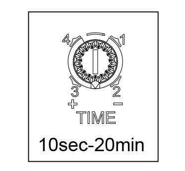
2. Delay adjustment knob:
The delay adjustment knob is responsible for managing the load time after the sensor triggers the work.
The knob can be set clockwise for a delay time of 10 seconds to 20 minutes. The user selects the appropriate position of the knob according to needs.
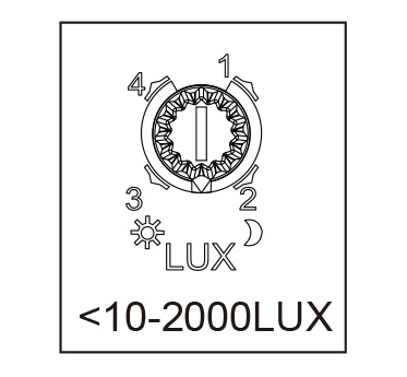
3.LUX adjustment knob:
LUX setting knob is used by the system to detect the ambient illumination, and it is the condition selection of the sensor under the circumstance of which the user chooses the ambient brightness that must be sensed. When the knob goes counterclockwise to the bottom, the sensor can only enter the induction when the brightness of the installed position is lower than 10LUX, that is, the sensor can only work in the dark hours at night. The higher the LUX value, the brighter the ambient brightness. Users can set the appropriate location according to their own needs.
4. D-TIME adjustment knob:
D-TIME knob is responsible for managing the adjustment of the standby brightness of the sensor. Knob clockwise direction can set 4 gears time. Users can set the appropriate location according to their own needs.
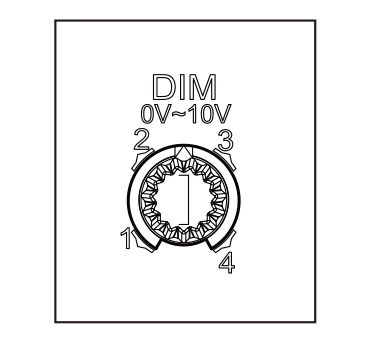
5.DIM setting knob:
DIM knob is responsible for managing standby brightness Settings. Knob clockwise direction can set 4 levels of brightness. Users can set the appropriate location according to their own needs.
Induction information
Product Testing
You can manually adjust work latency, sensitivity, ,light control values,D-TIME and DIM (for more information: knob settings);It is very convenient to use.Sensor suction Top Mounting height 2.5~4.5 m (Installation details: Installation instructions), and wiring according to the wiring diagram.Switch on the power supply, about 1 minutes after the sensor into a stable working state.Here, adjust the delay time to a minimum and adjust the light control value to the sun for testing.If you finished all testing, you can make time delay, light control value and sensitivity settings according to your needs, and the installation is complete.
Parameter setup Method: potentiometer
The following settings may require multiple adjustments to meet your requirements.
|
(1)Light-control setting
The work illumination value can be adjusted <10-2000LUX range.
The working illumination value is about 10 LUX when the counterclockwise rotation is in the end, and the working illumination value is about the day when the clockwise spin is in the end.
|
 |
|
(2)Delay setting
The delay time of the four gears is: 1:10s 2:1min 3:6min 4:20min
|
 |
Note: After the lights turn off, it takes nearly 4 seconds for it to sense again.The light will only light up when the signal is detected at the end of this time.
Correct use of delay adjustment: It is used to adjust the delay time of the sensor to detect the light after the body moves and lights up to the automatic extinguishing lamp.Users can adjust according to actual requirements.Because the infrared induction products have continuous sensing function, in short, the sensor in the delay time before the end of any induction, the system will be re-timed, as long as the person in the detection range of activities, the lamp will not be extinguished.Therefore, it is recommended that users try to adjust the delay time to achieve energy saving.
|
(3)Detection distance setting (sensitivity)
Four detection ranges are: 1:2m 2:8m 3:10m 4:16m
|
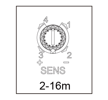 |
Attention:when using the product, please adjust the product sensitivity to the appropriate position, do not adjust the product sensitivity to the maximum, to avoid improper operation caused by wind starting curtains,
leaves, small animals, power grid and electrical equipment, which may cause the product not to work properly. When it is found that the product does not work properly, the user can try to lower the sensitivity appropriately before carrying out the test. Before or during the installation of the product, if the functional test is carried out, the personnel must leave the product sensor area and do not walk around to prevent continuous work of the sensor due to human movement.
|
(4)D-TIME setting
The standby time of the four gears is: 1:off 2:10min 3:20min 4. Automatic semi-bright at night
|
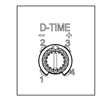 |
Note: when the light control value >200LUX, the product will exit the semi-bright mode.
|
(5)DIM setting
The brightness of standby gear four is: 1:5% Brightness 2:10% Brightness 3:20% Brightness 4:30% Brightness
|
 |
|
When choosing the 15-key remote controller, please read through the instruction below, you will find more functions.
Functions: ON- ON mode, in ON mode, the LED indicator in sensor will flash once a second, the load connected will keep working for 6 hours and then automatically turn to AUTO mode.
|
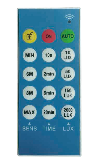 |
AUTO-auto-sensing mode: When signal detected, the LED indicator in sensor will flash once.
UNLOCK – press UNLOCK and start setting. If you do not make any setting, the system will be locked in 2 minutes, that is you are not allowed to modify settings. If you do make settings, the system will be locked 5 seconds after the last setting, that is you are not allowed to modify settings.
SENS-- set sensibility, MIN,6m,8m,MAX can be chosen.
TIME--- set time delay, 10”,2’,6’,20’ can be chosen.
LUX---- set working light, 10,50,150,2000(LUX)can be chosen.
After all above selected, press OK or SEND to start the settings and the sensor works as the controller settings.
NOTE: the controller is inside with CMOS that can memorize all the effective settings!
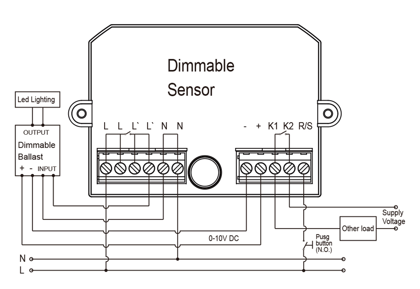
Connection
Installation is based on the wiring diagram provided.
|
|
TEST key : when the line is connected successfully and the control panel is not installed, press this key to TEST whether the load is connected normally. Note: press once to switch on the load, and the indicator light is always on; Press again to disconnect the load and extinguish the indicator. |
|
R port control: It can touch any point of L/N once to switch on the main control relay and close it within the delay time.
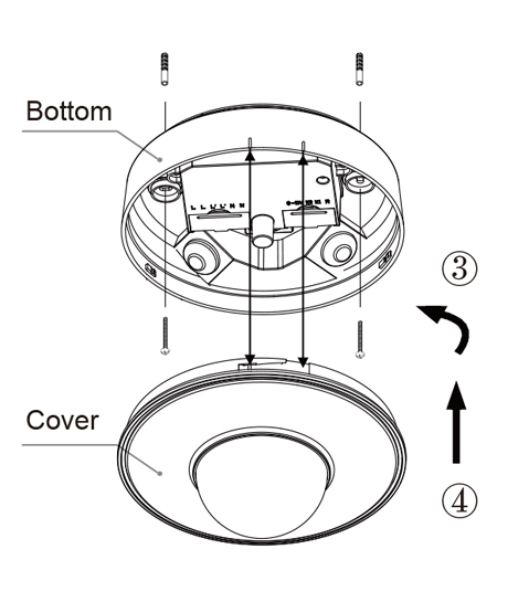
Installation
(1)The power supply should be cut off before installation;
(3)Install the bottom cover and screw (such as ③) ;
|
 |
Installation Attention
Ask an electrician or a person with relevant experience to install;
Do not use volatile objects as mounting substrates;
There should be no obstacles, non-stop moving objects in front of the detection window that affect its detection;
Do not install in areas where the airflow has changed significantly;Such as: Air conditioning, heating fan;
If the sensor is found to be faulty after installation, For your safety please do not open the sensor housing without permission.
Remark:
Install the probe toward the area that people often pass when installing。
Move the probe in the direction of the ambient light source for more accurate illumination settings。
Detect the signal again within the induction delay time, and the delay time will be superimposed。
Light-controlled LUX Knob: refers to the working environment illumination;When the knob is clockwise to the end, the whole day in the inductive state;When the knob is counterclockwise to the end, illumination <10LUX to enter the inductive state.
Delay Time Knob: refers to the lamp to receive the inductive signal after the light to no subsequent induction signal, the lamp work stage value。
Some problem and solved way
Load does not work:
a. Check that the power supply, load connection is correct;
b. Load is intact;
c. Check that the working illumination set by the sensor is consistent with the ambient illumination.
Low Sensitivity
a. Check if there are obstacles in front of the probe window that affect the sensor receiving signal;
b. Check if the ambient temperature used by the sensor is too high;
c. Check if the inductive signal source is in the sensor's detection area.;
d. Check if the installation height is within the limits specified in this manual.
Sensor does not automatically turn off load:
a. Is there a continuous sensing signal in the detection area?
b. Whether to set the sensor's work delay to the Max;
c. Whether the power supply used corresponds to the requirements in the instruction manual;
d. If there are significant changes in temperature near the sensor, such as air conditioning, heater and other equipment.
e. Whether the direction of movement is correct.
This manual for the content of this product programming at time, We will not notice if there are any updates.
The contents of the instruction manual are strictly prohibited for any reproduction by other purposes without the permission of the company.